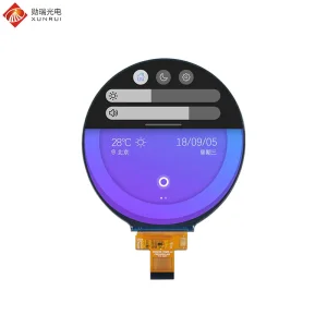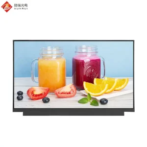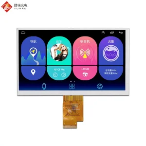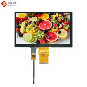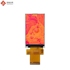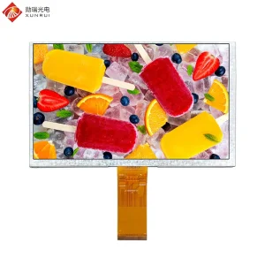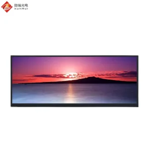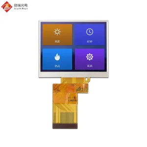
High-Performance TFT LCD Displays & Touch Solutions
Explore standard, customized, and wide-temperature liquid crystal display modules fabricated to strict ISO 9001 and ISO 14001 industrial benchmarks. Complete with custom FPC, high-nit backlights, and driver boards.
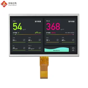
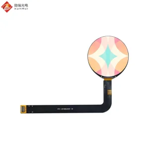
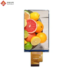
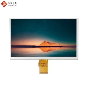
Engineering the 6.2-Inch Resistive Display: Form Factor Architecture & Physics
In modern industrial automation, vehicular avionics, and heavy outdoor instrumentation, capacitive touch often falls short when confronted with heavy conductive fluids, extreme electromagnetic noise (EMC/EMI), or operators donning heavy insulated work gloves. Here, the 6.2-inch resistive screen stands as an irreplaceable, bulletproof human-machine interface (HMI).
Measuring diagonally at 6.2 inches (typically with active viewing areas around 137.52 mm × 77.23 mm and standard 16:9 or double-DIN automotive aspect ratios), this display strikes an optimal balance between spatial compactness and comprehensive data visualization. Originating from high-yield 800×480 WVGA architectures and scaling up into specialized high-definition formats, the 6.2" resistive touchscreen functions via mechanical pressure that bridges two micro-separated electrically conductive layers: an Indium Tin Oxide (ITO) coated optical film on top, and an ITO-sputtered glass substrate beneath.
Separated by microscopic, invisible silicone spacer dots (ranging from 0.035 mm to 0.05 mm in height and pitched at calculated intervals to balance touch sensitivity and optical Newton's ring mitigation), an applied physical force of 20 to 100 grams causes dynamic physical contact between the conductive surfaces. A constant DC gradient applied across the X and Y axes calculates voltage drops directly proportional to the coordinates of the touch point. This analog voltage is digitized via high-precision 10-bit or 12-bit ADC controllers (such as TSC2046, AR1021, or custom AEC-Q100 certified automotive ICs), delivering immune coordinate tracking unaffected by surface wash-down, airborne saline, static discharge, or electrical motor arcing.
Why Global OEMs Partner with China 6.2" Resistive Screen Factories
Sourcing directly from Shenzhen and the Pearl River Delta electronics manufacturing corridor unlocks structural competitive advantages that cannot be replicated elsewhere.
Full Vertical Integration
Chinese tier-1 display factories control the entire manufacturing vertical: raw mother glass precision cutting, chemical thinning, automatic ITO vacuum sputtering, Chip-On-Glass (COG) and Film-On-Glass (FOG) hot-bar bonding, SMT driver board population, cleanroom OCA lamination, and final module encapsulation within ISO-certified facilities.
BOM Cost Efficiency
Direct access to localized glass substrates (BOE, HannStar, Innolux), optical film polarizers (Nitto Denko, Sanritz, domestic equivalents), high-efficiency Nichia or Epistar LED backlight dies, and precision injection tooling allows Chinese suppliers to deliver premium-grade 6.2-inch resistive displays at 30% to 45% lower capital cost than Western or Japanese integrators.
Rapid NPI & Prototyping Cycles
Rapid New Product Introduction (NPI) workflow ensures custom mechanical drawings and FPC schematics are delivered within 48 to 72 hours. Prototype sample fabrication is completed within 12 to 18 calendar days, backed by a flexible 5 to 500 pcs trial run before tooling lock-in and volume mass-production launch.
Guaranteed Long-Term Availability
Industrial and medical projects demand lifecycle stability of 5 to 10+ years. Chinese factories establish long-term cell wafer agreements and strategic driver IC silicon stockpiles. When an upstream glass cut goes end-of-life (EOL), internal engineering redesigns pin-compatible drop-in replacements with zero redesign impact to the customer's chassis.
Cleanroom Optical Bonding
Xunrui's Shenzhen plant houses Class 1,000 and Class 100 cleanrooms equipped with automated Optical Clear Adhesive (OCA) and Optical Clear Resin (OCR) lamination machinery. By vacuum bonding the 6.2-inch resistive touch sensor directly to the TFT LCD polarizer, internal air gaps are eliminated, boosting contrast ratios up to 400% in bright ambient conditions.
Custom Engineering Tailoring
Total customization capabilities: high-brightness backlight LED arrays delivering from 350 to 1,500+ nits for direct sunlight readability, wide-temperature liquid crystal fluid operating between -30°C and +85°C, bespoke FPC trace routings, EMI shielding mesh layers, and custom anti-glare (AG) or anti-reflective (AR) surface treatments.
4-Wire vs. 5-Wire Resistive Architectures: Technical Selection Guide
Selecting the correct resistive topology is the single most critical engineering decision when specifying a 6.2-inch display module. Compare optical, electrical, and mechanical parameters below.
| Performance Specification | 4-Wire Resistive (4WRTP) | 5-Wire Resistive (5WRTP) | Resistive Multi-Touch (RMTS) | Projected Capacitive (PCAP) Reference |
|---|---|---|---|---|
| Operating Principle | Dual-layer coordinate measurement (X on top, Y on bottom) | All coordinate axes driven through bottom glass; top film acts only as voltage probe | Segmented matrix or multi-zone analog resistive switching | Electrostatic field capacitance disruption (charge transfer) |
| Point Actuation Durability | 1 Million to 3 Million Touches | 35 Million+ Touches | 5 Million to 10 Million Touches | 50 Million+ Touches (Glass wear limited) |
| Optical Transmittance (%) | 78% – 82% | 80% – 85% | 76% – 80% | 88% – 92% |
| Input Medium | Bare finger, heavy glove, stylus, pen, blunt object | Bare finger, heavy glove, stylus, pen, blunt object | Bare finger, gloved hand, dual styluses | Conductive medium only (bare skin, conductive gloves) |
| Water / Fluid Immunity | 100% Immune to standing water, grease & sprays | 100% Immune to standing water, grease & sprays | High immunity; minor software algorithm compensation | Prone to false triggers (ghost touches) without firmware tuning |
| EMC / EMI Resistance | Exceptional (Purely DC resistance based) | Exceptional (Purely DC resistance based) | Very High | Requires intense hardware filtering & shielding |
| Thermal Operating Range | -20°C to +70°C | -30°C to +85°C | -20°C to +70°C | -20°C to +70°C (Extended with premium ICs) |
| Tooling & Unit Cost | Lowest / Ideal for budget-conscious volume | Moderate / High ROI for heavy industrial | Higher / Specialized controller required | Moderate to High / Tooling for custom cover glass |
Why 5-Wire Resistive Technology Dominates Critical 6.2" Deployments
In standard 4-wire resistive panels, constant physical actuation over the exact same pixel zone (such as an onscreen "START" or "CONFIRM" virtual button) gradually degrades the microscopic ITO layer on the flexible upper PET film. Once micro-fractures occur in this upper conductive layer, electrical resistance shifts, resulting in calibration drift, unresponsiveness, or catastrophic failure.
In contrast, 5-wire resistive architecture places both the X and Y coordinate resistor networks entirely upon the rigid bottom glass substrate. The upper flexible polyester film is solely coated with a uniform conductive layer acting strictly as a passive voltage-measuring sensor. Even if the flexible top sheet experiences localized mechanical fatigue or micro-scratching, the voltage measurement taken at the point of contact remains mathematically unaltered. For heavy-duty 6.2" vehicle consoles, commercial fleet displays, and petroleum terminals, 5-wire resistive screens provide virtually indestructible field longevity.
Global Industry Solutions: 6.2-Inch Resistive Display Applications
From extreme sub-zero agricultural telematics to explosive chemical refining installations, examine how the 6.2-inch resistive display architecture resolves critical operating challenges across diverse industries.
Automotive 2-DIN & Fleet Telematics
The 6.2-inch footprint is the universally recognized worldwide standard for double-DIN center-console infotainment, commercial trucking Electronic Logging Devices (ELD), and construction cab telemetry. In heavy excavators, tractors, and mining haulers, operators wear leather gloves while cabin temperatures fluctuate from -25°C in Arctic winter to +65°C under desert sun. Resistive touch guarantees faultless interaction without false triggering caused by cabin vibrations or condensation.
Industrial HMI & CNC Controllers
Factory floors are saturated with heavy electromagnetic interference generated by Variable Frequency Drives (VFDs), welding arcs, and high-power servo motors. Where PCAP screens generate severe phantom touches from conducted high-frequency electrical noise, the DC analog circuit of a 6.2" resistive screen remains immune. Machine operators can safely calibrate CNC tool paths, set PLC parameters, and operate emergency stops while handling cutting lubricants.
Medical Diagnostics & Surgical Monitors
Modern intensive care units and surgical suites enforce stringent sterile operating protocols. Medical staff must operate bedside infusion pumps, blood gas analyzers, and portable defibrillators while wearing multiple layers of sterile latex or nitrile gloves. Resistive 6.2-inch screens function through all barrier materials and are sealed with antimicrobial surface films resistant to hospital-grade sterilization agents, alcohol wipes, and bleach solutions.
Explosion-Proof (ATEX / IECEx) Terminals
In petrochemical refineries, underground coal mining, and grain processing facilities, electronic displays must achieve strict intrinsic safety ratings (Zone 1/Zone 2 ATEX). The low voltage and low energy storage characteristics of 4-wire and 5-wire resistive screens mean that, even in the event of severe enclosure cracking or blunt impact, the touch assembly cannot produce an incendiary electrical arc.
Marine Navigation & Fishfinders
Salt spray, direct solar radiation, and rain squalls render conventional capacitive screens unusable on open boat flybridges. By pairing a 6.2-inch resistive screen with a 1,000+ nit high-brightness LED array and optical bonding, marine GPS chartplotters and sonar echo-sounders remain fully sunlight readable and 100% functional even when sea wash runs down the faceplate.
Defense, Security & Tactical Systems
Portable military communications gear, rugged field computers, and perimeter surveillance consoles require zero stray electromagnetic emissions and complete operational reliability in muddy, soaked, or sandy environments. Resistive 6.2-inch panels paired with night vision goggle (NVG) compatible optical filters deliver dependable situational awareness under the harshest field deployments.
Rigorous 5-Gate Quality Assurance & Manufacturing Workflow
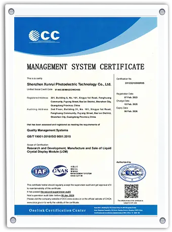
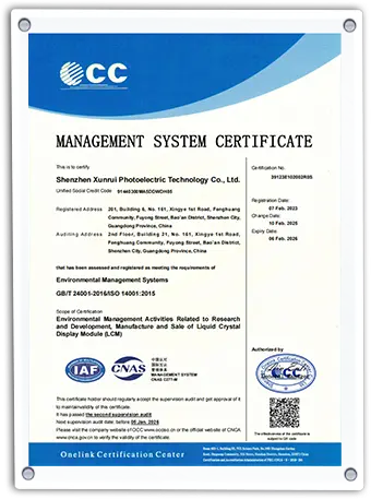
Shenzhen Xunrui Optoelectronic Technology operates under certified ISO 9001 and ISO 14001 systems. Every custom 6.2" resistive screen module passes through 5 comprehensive engineering inspection gates before release.
Gate 1: IQC Incoming Inspection
100% spectroscopic testing of raw ITO glass resistivity, optical transmittance verification, polar film visual inspection under polarizing lamps, and strict dimensional verification of incoming flexible printed circuits (FPCs) and backlight frames.
Gate 2: COG / FOG Laser Bonding
Automated cleanroom anisotropic conductive film (ACF) attachment, high-precision micro-pitch optical alignment (tolerance ±3μm), hot-bar pressure bonding, and automated microscopic AOI inspection of gold bump conductive connections.
Gate 3: Thermal Aging Screening
Every active cell module undergoes 72 hours of uninterrupted dynamic burn-in and thermal cycle screening (-30°C to +85°C) inside environmental stress chambers to weed out latent electrical component or liquid crystal seal weaknesses.
Gate 4: Touch Linearity Testing
Multi-axis computerized robotic testing probes the entire 6.2" touch perimeter. Resistance linearity across X and Y axes must demonstrate less than 1.5% deviation. Chattering time is checked to guarantee ≤10ms response speed.
Gate 5: Outgoing Quality Control (OQC) Environmental Torture Testing
Before batch release, samples from every production lot undergo mechanical ball drop tests (steel ball drop impact resistance), 250g stylus abrasion testing (exceeding 200,000 passes), electrostatic discharge testing (±8kV contact, ±15kV air discharge meeting IEC 61000-4-2 standards), and salt spray corrosion testing (48 hours at 35°C with 5% NaCl solution). This guarantees zero out-of-box defects when shipments arrive at overseas integration facilities in North America, Europe, or the Asia-Pacific region.
Global B2B Buyer's Guide: Sourcing 6.2" Resistive Screens
Key technical parameters hardware engineering directors, sourcing leads, and product architects must evaluate when defining custom display specifications.
Electrical & Optical Integration Checklist
1. Driver Interface Architecture: Choose between TTL RGB 24-bit (standard for embedded MCUs like NXP i.MX6 or STM32), LVDS (for noise-immune signal transmission over longer chassis distances), or modern MIPI DSI interfaces.
2. Optical Lamination Type: Frame air bonding (cost-effective) vs. Full OCA Optical Bonding (drastically cuts internal light reflection from 4.5% to under 0.2%, maximizing outdoor readability).
3. Backlight Lifetime & Thermal Dissipation: Industrial-grade LEDs offering ≥50,000 hours to half-brightness (L50), configured with aluminum heat-sink back-planes to prevent thermal trapping within sealed NEMA or IP67 enclosures.
Supply Chain & Project Risk Mitigation
1. NRE & Custom Tooling Transparency: Review FPC layout, custom bezel stamping, and backlight enhancement tooling fees upfront. Xunrui provides full refund structures for NRE tooling upon reaching agreed volume tiers.
2. Multi-Sourced Driver Silicon: Ensure the factory qualifies at least two second-source controller ICs (e.g., Sitronix, Ilitek, or Himax) to safeguard production runs against global semiconductor supply choke points.
3. Trial Batch De-Risking: Always demand a gated trial batch (5 to 500 pcs) after first-article sample signoff. This allows field hardware verification, firmware driver calibration, and vibration chassis testing prior to committing to 1,000+ pcs mass-production runs.
Certified Systems & Global Enterprise Network
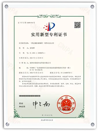
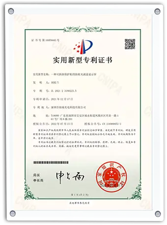
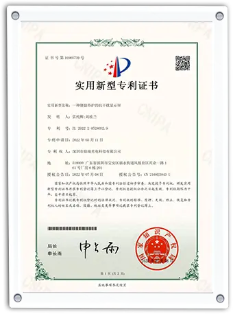
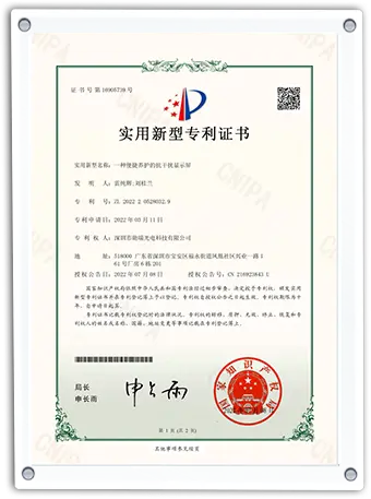
Shenzhen Xunrui Optoelectronic Technology Co., Ltd. is a nationally certified High-Tech Enterprise holding multiple utility model patents, operating under ISO 9001 quality management and ISO 14001 environmental safety certifications.











Frequently Asked Questions: 6.2" Resistive Screen Engineering & Sourcing
Direct answers from Xunrui's optoelectronic application engineers covering electrical integration, durability, optical clarity, calibration, and procurement protocols.
What are the standard mechanical and optical specifications of a 6.2-inch resistive display?
Why choose a 6.2" resistive screen over a capacitive (PCAP) touchscreen for industrial applications?
How does Xunrui solve the lower optical clarity traditionally associated with resistive touch screens?
What is the difference between 4-wire and 5-wire resistive touch panels on 6.2" displays?
What controller ICs and interfaces are supported for 6.2" resistive screen integration?
What is the minimum order quantity (MOQ) and customization lead time for overseas OEM buyers?
Can the 6.2" resistive screen operate in extreme sub-zero or high-temperature environments?
How does Xunrui protect custom display programs from component obsolescence (EOL)?
High-Precision TFT LCD Modules & Custom Enclosures
Explore round, bar-type, capacitive touch, and ultra-wide liquid crystal displays engineered for intelligent devices, medical instruments, and automotive HMIs.