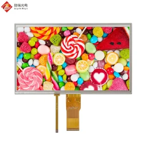
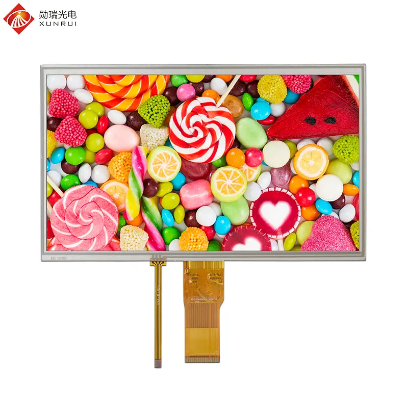
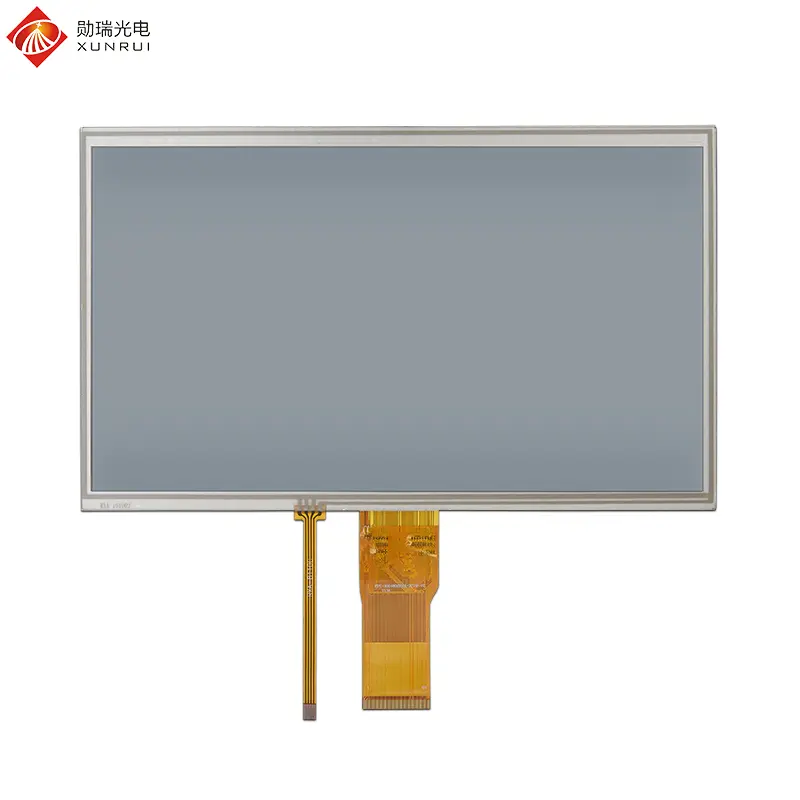
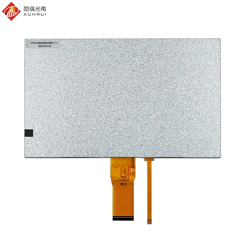
Custom 10.1 inch 1024×600 TN TFT LCD display with resistive touch panel Supplier, Suppliers
Product Description
Product Description
Screen Size
10.1 Inch
Resolution
1024 × 600
Brightness
260 cd/m²
Touch Type
Resistive Touch
Mechanical Drawing

Specification Parameters
| Feature | Spec |
|---|---|
| Model Name | H101IWS50E3501-T1 |
| LCD Size | 10.1 inch |
| Display Format | 1024×600 |
| Interface | RGB 50pin |
| Luminance | 260 cd/m² |
| Touch Screen | Resistive Touch |
| Viewing Direction | 6 O’ Clock |
| Color Depth | 16.7M |
| Driver IC | EK79001HM + Gate EK73215BCGA |
| LCM + RTP (W × H × D) (mm) | 235 (W) × 143 (H) × 6.5 (T) |
| Active Area (mm) | 222.72 (W) × 125.28 (H) |
| Operating Temperature | -10℃ ~ +60℃ |
| Storage Temperature | -20℃ ~ +70℃ |
| Operating Voltage | 9.6V |
Interface Definition
| Pin No. | Symbol | I/O | Function / Description |
|---|---|---|---|
| 1 ~ 2 | LEDA | P | LED Anode (Backlight LED Cathode VBL-) |
| 3 ~ 4 | LEDK | P | LED Cathode |
| 5 | GND | P | Ground |
| 6 | VCOM | P | Common Voltage |
| 7 | DVDD | P | Digital Power |
| 8 | MODE | I | DE/SYNC Mode Select (MODE=H: DE Mode normally pull high; MODE=L: HSD/VSD Mode) |
| 9 | DE | I | Data Enable Signal |
| 10 | VS | I | Vertical Sync Input (Negative Polarity) |
| 11 | HS | I | Horizontal Sync Input (Negative Polarity) |
| 12 ~ 19 | B7 ~ B0 | I | Blue Data Input |
| 20 ~ 27 | G7 ~ G0 | I | Green Data Input |
| 28 ~ 35 | R7 ~ R0 | I | Red Data Input |
| 36 | GND | P | Ground |
| 37 | DCLK | I | Clock Input |
| 38 | GND | P | Ground |
| 39 | L/R | I | Source Right or Left Sequence Control (SHLR=H: Right shift, Left → Right [Default]; SHLR=L: Left right, Right → Left) |
| 40 | U/D | I | Gate Up or Down Scan Control (UPDN=H: Up shift, Down → Up; UPDN=L: Down shift, Up → Down [Default]) |
| 41 | VGH | P | Positive Power for TFT |
| 42 | VGL | P | Negative Power for TFT |
| 43 | AVDD | P | Power for Analog Circuit |
| 44 | RESET | I | Global Reset Pin. Active low to enter reset state. Suggest connecting with an RC reset circuit for stability (Normally pull high: R=10K, C=1μF). |
| 45 | NC | - | Not Connected |
| 46 | VCOM | P | Common Voltage |
| 47 | DITHB | I | Dithering Function |
| 48 | GND | P | Ground |
| 49 ~ 50 | NC | - | Not Connected |
Featured Products
2 inch 480×240 RGB 40pin 150nit TN TFT LCD Display
2.4 inch 240×320 MCU 40pin interface 250nit TN TFT LCD module
2.8 inch 240×320 MCU 30pin interface 250nit TN TFT LCD display
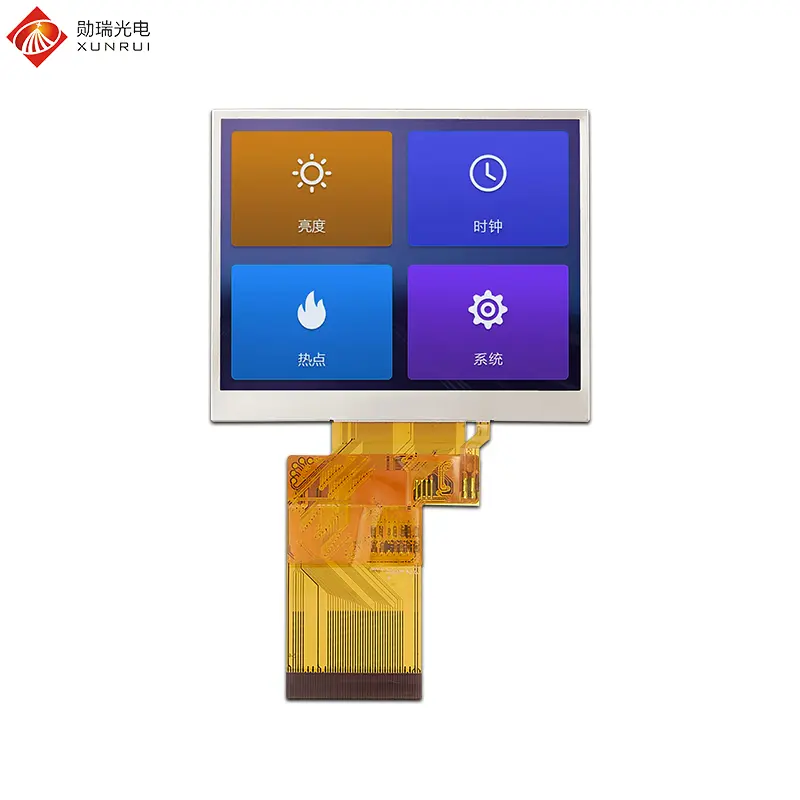
3.5 inch 320×240 RGB 54pin interface 350nit TN TFT LCD module
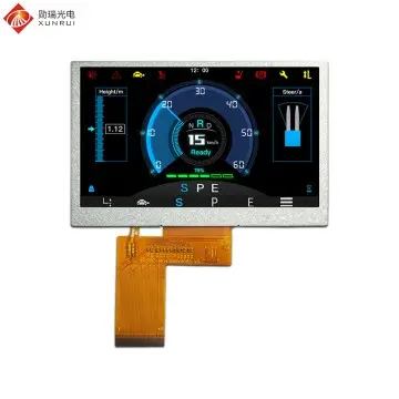
4.3 inch TFT LCD 800×480 RGB 40pin interface 300nit IPS module
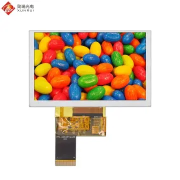
5 inch 800×480 1200nit High brightness TN TFT LCD module
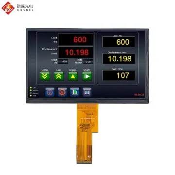
7 inch 1024×600 1000nit High brightness IPS TFT LCD module
8 inch TFT LCD module 800×1280 MIPI 31pin interface 480nit IPS screen
10.1 inch TFT LCD module 1280×800 LVDS 40pin interface 350nit IPS screen
13.3 inch 1920×1080 EDP 30PIN 280nit IPS TFT LCD Module
Frequently Asked Questions
What makes the H101IWS50E3501-T1 LCD ideal for harsh industrial environments?
The module features an integrated resistive touch panel that responds to pressure rather than capacitance. This allows reliable input even when users wear heavy gloves or utilize non-conductive styluses, ensuring flawless interaction in conditions exposed to moisture, airborne dust, or oil.
What interface and driver controllers are used in this 10.1-inch module?
It communicates through a standard 50-pin RGB parallel interface and is powered by the EK79001HM source driver combined with the EK73215BCGA gate driver IC, providing robust data processing and support for up to 16.7M colors.
Can the scanning and display orientation be inverted on this display?
Yes, pins 39 (L/R) and 40 (U/D) provide directional scan control. Pin 39 switches horizontal shift from left-to-right to right-to-left, while Pin 40 shifts vertical scanning from down-to-up or up-to-down, enabling reverse mounting orientations.
What are the operational temperature limits for this display?
The module operates safely within a temperature range of -10℃ to +60℃, and can be stored in conditions ranging from -20℃ to +70℃, ensuring compatibility with standard industrial and vehicular thermal profiles.
How should the reset pin (Pin 44) be integrated for maximum system stability?
Pin 44 is an active-low global reset. For optimal electrical stability and noise immunity, it is recommended to interface it with an RC reset circuit featuring a 10KΩ pull-up resistor and a 1μF capacitor.